MatrixHardware Header
Todo: describe the hardware header file here. Describe user-configurable settings and how to create a custom hardware header.
Documentation for the SmartLED Shield Hardware is hosted on another site: SmartMatrix Docs
HUB75 connectors usually have the same order of RGB colors on the pinout, but occasionally a manufacturer will ship a panel with the wrong color order. There's an easy fix for the Teensy platforms, but this hasn't been added to ESP32 yet, so you'll have to change the code manually.
- Get a sketch working on your panel, so you know which MatrixHardware file is appropriate for your panel.
- Figure out which colors are swapped, e.g. you can print the string "RED" to the screen with color set to red, and see what color it shows up on your screen, repeating for the color colors.
- Copy the MatrixHardware file from SmartMatrix Library into your sketch folder, and give it a unique name e.g. adding
_BGRto the name if your color order is reversed from normal RGB - Edit the MatrixHardware file to print a custom message on compilation, e.g. instead of
#pragma message "MatrixHardware: SmartLED Shield for Teensy 4 (V5)", it would say#pragma message "MatrixHardware: SmartLED Shield for Teensy 4 (V5) with BGR Color Order" - Change your sketch to use the local MatrixHardware file, e.g.
#include <MatrixHardware_Teensy3_ShieldV4.h>would change to#include "MatrixHardware_Teensy3_ShieldV4_BGR.h" - Test to make sure the sketch still compiles, and you get the custom error message you saw above
- Now edit the MatrixHardwareFile to swap the color order. Find the section labeled
// these defines control the color channel assignments - if your panel has non-standard RGB order, swap signals here. You can connect the color signal to the color pin. e.g. if your red and blue colors are swapped, your defines would look like this:
#define R_0_SIGNAL    FLEXIO_PIN_B0_TEENSY_PIN
#define G_0_SIGNAL    FLEXIO_PIN_G0_TEENSY_PIN
#define B_0_SIGNAL    FLEXIO_PIN_R0_TEENSY_PIN
#define R_1_SIGNAL    FLEXIO_PIN_B1_TEENSY_PIN
#define G_1_SIGNAL    FLEXIO_PIN_G1_TEENSY_PIN
#define B_1_SIGNAL    FLEXIO_PIN_R1_TEENSY_PIN
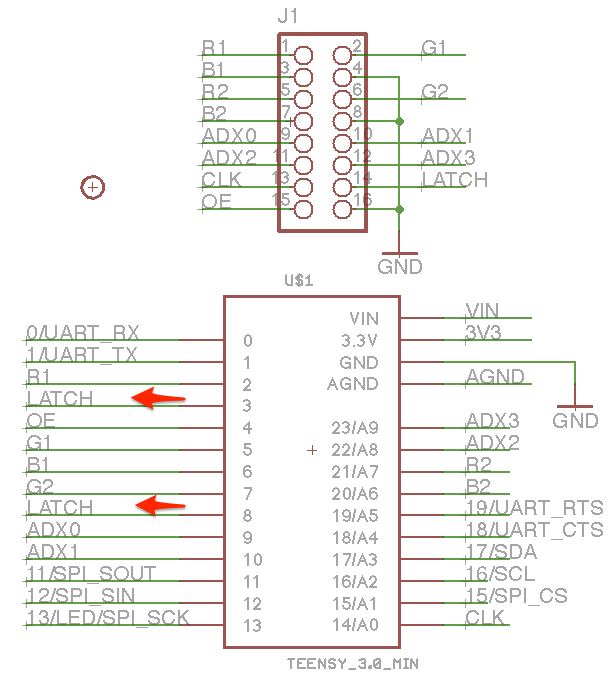
A Teensy 3 can be connected to the display panel using individual wires. Follow the wiring for the 13 signals between J1 and U1 in the SmartMatrix Shield schematic, as well as ground. Make sure to connect the LATCH signal to both pins on the Teensy, as well as the display connector.
Most panels are compatible with 3.3V signals, but some are not. Starting with V3, the SmartMatrix Shield includes 74AHCT245 buffers for all the signals going to the panel, to boost the signals closer to the 5V level some panels require. If you are seeing flickering or no LEDs lit when driving a panel, you may need to add buffers between the Teensy and panel.
If you want to use the improved circuit included in SmartLED Shield V4, that requires some external chips to drive the ADDX lines, freeing up more pins and other resources on the Teensy for other purposes. See the schematic and BOM for the circuit and parts needed.
The Teensy 4 port requires an external latch chip, there's no way to drive a HUB75 panel without that chip. See the schematic and BOM for the circuit and parts needed.