Control Gravity Compensation
Table of Contents generated with DocToc
Please check README.md on https://github.com/jhu-dvrk/dvrk-gravity-compensation instead.
In ideal case, given robot link mass and center of mass, Recursive Newton Euler (RNE) algorithm can be used to compute gravity compensation terms. To get this correct, we need two things:
- A correct implementation of RNE
- Robot model
- Kinematics: DH Parameters
- Dynamatics: Link mass & Center of Mass (COM)
In this section, we use a simple two link RR robot (RRBot in Gazebo tutorial) as a testbed for different robot kinematics and dynamics libraries in particular cisstRobot and KDL (See Appendix II). The robot parameters are known and described in an URDF file. Also MATLAB Robotics Vision & Control (RVC) toolbox is used as reference. Besides, we send computed values to Gazebo Simulator to visually check the values.
See:
- Gazebo tutorial: http://gazebosim.org/wiki/Tutorials/1.9/Using_A_URDF_In_Gazebo
- Code: https://github.com/ros-simulation/gazebo_ros_demos
- Code: https://github.com/ros-simulation/gazebo_ros_demos
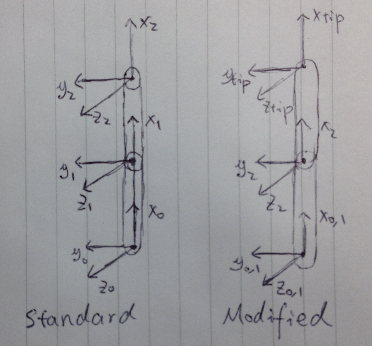
Table: Standard DH for RRBot
| Frame | Joint Name | alpha | a | d | theta |
|---|---|---|---|---|---|
| 1 | Joint 1 | 0 | 0.9 | 0 | q1 |
| 2 | Joint 2 | 0 | 0.9 | 0.1 | q2 |
Table: Modified DH for RRBot
| Frame | Joint Name | alpha | a | d | theta |
|---|---|---|---|---|---|
| 1 | Joint 1 | 0 | 0.0 | 0 | q1 |
| 2 | Joint 2 | 0 | 0.9 | 0.1 | q2 |
| 3 | Tip | 0 | 0.9 | 0 | 0 |
A Gazebo model plugin has been written for testing.
Code Repository: https://github.com/zchen24/gazebo_ros_demos
CisstRobot & KDL have been tested in this simple case using both Standard and Modified DH parameters.
| Cisst Robot | KDL | Matlab | |
|---|---|---|---|
| Kinematics Std | YES | YES | YES |
| Kinematics Mod | YES | YES | YES |
| Gravity Std | YES | YES | YES |
| Gravity Mod | NO | NO (? Not sure) | YES |
NOTE:
- center mass is with reference to link frame
- use Standard DH for dynamics
NOTE:
- COM is with reference to link frame (Standard DH)
- Unit: m, kg
Link 7: Wrist Roll
NOTE: no mass, information is integrated to link 6
Link 6: Wrist Yaw
| Link | Mass | COM | Comment |
|---|---|---|---|
| 6 | 0.05 | [0.0 -0.025 0.05] | Motor is heavy |
Link 5: Wrist Pitch
NOTE: Left / Right are mirrored, different COM
| Link | Mass | COM | Comment |
|---|---|---|---|
| 5 | 0.04 | [0.0 0.036 -0.065] | MTMR |
| 5 | 0.04 | [0.0 -0.036 -0.065] | MTML |
NOTE: massive spring here, don't know how to deal with this.
Link 4: Setup Joint (Platform)
NOTE: Left / Right are mirrored, different COM
| Link | Mass | COM | Comment |
|---|---|---|---|
| 4 | 0.14 | [0.0 -0.084 -0.12] | MTMR |
| 4 | 0.14 | [0.0 -0.084 0.12] | MTML |
Link 3: Outer Pitch 2 (Elbow)
| Link | Mass | COM | Comment |
|---|---|---|---|
| 3 | 0.04 | [-0.25 0.00 0.00] | Parallel Mechanism |
taugc = torque computed using RNE
tau(3) = taugc(3) - m * g * cos(q2 + q3)   // parallel
if (q[3] < 0.05) tau[3] += ((q[3] - 0.05) * 0.1 - 0.07);  // cable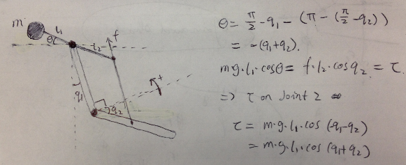
Link 2: Outer Pitch 1 (Shoulder)
| Link | Mass | COM | Comment |
|---|---|---|---|
| 3 | 0.65 | [-0.38 0.00 0.00] |
NOTE: huge mass at the top of this link, thus the COM is at the top.
tau[2] = taugc - 0.30    // 0.30 is offset for cable
if (q[2] < 0.05) tau[2] += (q[2] - 0.05) * 1.0 + 0.05   // cable
Link 1: Outer Yaw
| Link | Mass | COM | Comment |
|---|---|---|---|
| 1 | 0.00 | [0.00 0.00 0.00] |
// Cable MTMR at JHU
tau[1] = -0.1 * qd[1]    // add damping
if (q[1] > -0.15) tau[1] = tau(1) + (q[1] - (-0.15)) * 0.1 + 0.04;
NOTE:
- Disk set mass to 0, does not affect RNE computation
- Huge cable force
See:
Atkeson, Christopher G., Chae H. An, and John M. Hollerbach. "Estimation of inertial parameters of manipulator loads and links." The International Journal of Robotics Research 5.3 (1986): 101-119.
??? Anyone wants to try ???
Standard DH Parameters
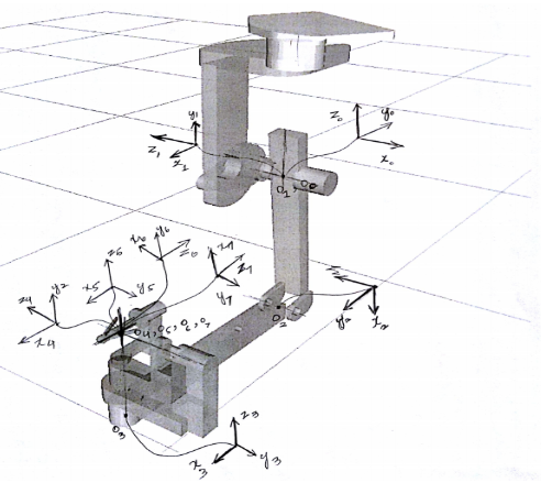
Image from Adnan Munawar (WPI)
Table 1: Standard DH for MTM
| Frame | Joint Name | alpha | a | d | theta |
|---|---|---|---|---|---|
| 1 | Outer Yaw | pi/2 | 0 | 0 | q1 - pi/2 |
| 2 | Outer Pitch 1 | 0 | l_arm | 0 | q2 - pi/2 |
| 3 | Outer Pitch 2 | -pi/2 | l_forearm | 0 | q3 + pi/2 |
| 4 | Setup Joint | pi/2 | 0 | h | q4 |
| 5 | Wrist Pitch | -pi/2 | 0 | 0 | q5 |
| 6 | Wrist Yaw | pi/2 | 0 | 0 | q6 - pi/2 |
| 7 | Wrist Roll | 0 | 0 | 0 | q7 + pi/2 |
Modified DH Parameters
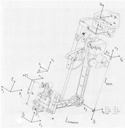
Image from ISI da Vinci Research Kit Manual
| Frame | Joint Name | alpha | a | d | theta |
|---|---|---|---|---|---|
| 1 | Outer Yaw | 0 | 0 | 0 | q1 + pi/2 |
| 2 | Outer Pitch 1 | -pi/2 | 0 | 0 | q2 - pi/2 |
| 3 | Outer Pitch 2 | 0 | -l_arm | 0 | q3 + pi/2 |
| 4 | Setup Joint | pi/2 | -l_forearm | h | q4 |
| 5 | Wrist Pitch | -pi/2 | 0 | 0 | q5 |
| 6 | Wrist Yaw | pi/2 | 0 | 0 | q6 + pi/2 |
| 7 | Wrist Roll | pi/2 | 0 | 0 | q7 + pi/2 |
Kinematics and Dynamics Library (KDL) is a library that supports chain/tree like manipulator kinematics and dynamics computation. By default, it uses frame to represent adjacent joint/link relations, which is more flexiable. DH parameter is also supported as showed in the following code snippet.
Table: Standard DH for RRBot
| Frame | Joint Name | alpha | a | d | theta |
|---|---|---|---|---|---|
| 1 | Joint 1 | 0 | 0.9 | 0 | q1 |
| 2 | Joint 2 | 0 | 0.9 | 0 | q2 |
#include <kdl/chainfksolverpos_recursive.hpp>
#include <kdl/chainidsolver_recursive_newton_euler.hpp>

// Construct KDL
KDL::Chain RRBotKdl;
inert = KDL::RigidBodyInertia(1.0, KDL::Vector(-0.45, 0, 0),
                              KDL::RotationalInertia(1, 1, 1, 0, 0, 0));
RRBotKdl.addSegment(KDL::Segment(KDL::Joint(KDL::Joint::RotZ),
                    KDL::Frame::DH(0.9, 0.0, 0.0, 0.0), inert));
RRBotKdl.addSegment(KDL::Segment(KDL::Joint(KDL::Joint::RotZ),
                    KDL::Frame::DH(0.9, 0.0, 0.1, 0.0), inert));

// Get some joint pos, vel, acc values
KDL::JntArray jnt_q(mNumJnts);
KDL::JntArray jnt_qd(mNumJnts);
KDL::JntArray jnt_qdd(mNumJnts);
KDL::JntArray jnt_taugc(mNumJnts);
KDL::Wrenches jnt_wrenches;
for (unsigned int i = 0; i < mNumJnts; i++) {
  jnt_q(i) = q[i];
  jnt_qd(i) = 0.0;
  jnt_qdd(i) = 0.0;
  jnt_wrenches.push_back(KDL::Wrench());
}

// Kinematics
KDL::ChainFkSolverPos_recursive fkSolver = KDL::ChainFkSolverPos_recursive(RRBotKdl);
KDL::Frame fkKDL;
fkSolver.JntToCart(jnt_q, fkKDL);

// Compute Dynamics
KDL::Vector gravity(-9.81, 0.0, 0.0);
KDL::ChainIdSolver_RNE gcSolver = KDL::ChainIdSolver_RNE(RRBotKdl, gravity);
ret = gcSolver.CartToJnt(jnt_q, jnt_qd, jnt_qdd, jnt_wrenches,jnt_taugc);
if (ret < 0) ROS_ERROR("KDL: inverse dynamics ERROR");
NOTE: Support both standard & modified DH Wrenches
Reference:
- ROS Answers: http://answers.ros.org/question/9545/kdl-for-arm/
- NOTE: Jon Bohren mentioned first joint should be fixed, don't understand why
- http://www.orocos.org/wiki/orocos/kdl-wiki
% start rvc toolbox
startup_rvc

% construct DH robot

% L(1) 1st Revolute
L(1) = Link([0 0 0 pi/2 0]);
L(1).offset = -pi/2;
L(1).m = 0.00;
L(1).r = [0 0 0];
L(1).I = [0.001, 0.001, 0.001, 0, 0, 0];
L(1).G = 1;
L(1).Jm = 0.0;

% L(2) 2nd Revolute
L(2) = Link([0 0 l_arm 0 0]);
L(2).offset = -pi/2;
L(2).m = 0.10;
L(2).r = [-0.1794, 0, 0];
L(2).I = [0.001, 0.001, 0.001, 0, 0, 0];
L(2).G = 1;
L(2).Jm = 0.0;

% Create Serial Link
rob = SerialLink(L, 'name', 'Two link robot', ...
    'manufacturer', 'Zihan');


% Forward Kinematics
rob.fkine(q)

% Gravity
rob.gravload(q)
NOTE: it also supports symbolic computation
List of codes:
- mdl_mtm.m: create MTM model with standard DH
- mdl_mtm_modified.m: create MTM model with modified DH
- mdl_psm.m: create PSM model with modified DH
Reference:
- Robotics, Vision and Control by Peter Corke
- Chapter 5: kinematics
- Chapter 7: dynamics
- NOTE: more examples can be found in the book

Community
Getting Started
- First Steps
- Software installation
- Controller Connectivity
- Configuration files
- Hardware Setup
- Calibration
- Classic/Standard
- Si
- Examples
Advanced
- Software Architecture
- Application Development
- APIs
- UI Customization
- Teleoperation
- Kinematics Simulation
- Potentiometer Issues
- Development Branches
- Release Checklist
- Projects
- Controllers/versions
- E-STOP Wiring
- Full da Vinci System
- Head Sensor
- Foot Pedals
- Video
- Instruments
Miscellaneous
- Frequently Asked Questions
- User manuals Classic and Si moved
- QLA Heat Sink
- Build w/o ROS Linux Mac
- cisst
- JHU
Deprecated