Robot URDF configuration
This Document covers:
- Explanation of robot URDF configuration.
- Modification of the position and/or orientation of the gripper with respect to the robot arms.
- Modification of the Tool Center Points (TCP's)
- Modification of gripper models
Note: The URDF files for the 85mm and 140mm Robotiq 2 Finger Adaptive Grippers can be found in Danfoa/robotiq_2finger_grippers
Some understanding of this files formats is required to completely comprehend how the robot is configured, nevertheless without any knowledge on this file formats you should still be able to do what you want to do.
URDF (Universal Robot Description Files) is the standard way of describing a robot in ROS, it is an XML file composed of Links (robot parts) and Joints (unions of two links), which has information of the relative position and orientation of all parts of the robot and the nature of its actuated and non-actuated joints.
XACRO is a ROS package with which you can construct shorter and more readable XML files by using macros that expand to larger XML expressions. In the case of URDF, it allows constructing robot description files in a more modular and scalable way. That is why this repository uses XACRO files mostly.
NOTE: If you want to get more insights into URDF and XACRO files, see the original URDF tutorials
The invite_csda10f.xacro file that is located in the invite_motoman_support/urdf folder, is in charge of defining and joining the robot and its grippers, please open it to see the code and launch it to see it in action.
roslaunch invite_motoman_support test_csda10f.launch
In the first section of the file we import three .xacro files to construct our robot: The robot itself, and the right and left robotiq grippers with strokes 140 and 85mm respectively.
<!-- Import macros required-->
        <!--Import macro for the CSDA10F robot-->
	<xacro:include filename="$(find motoman_csda10f_support)/urdf/csda10f_macro.xacro" />
	<!--Import macro for left arm gripper-->
  	<xacro:include filename="$(find invite_motoman_support)/urdf/left_gripper_macro.xacro" />
  	<!--Import macro for right arm gripper-->
  	<xacro:include filename="$(find invite_motoman_support)/urdf/right_gripper_macro.xacro" />
Then once we proceed to instanciate each of the xacros.
<!--Create instance of the macros imported-->
	<!--Create an instance of YASKAWA Motoman CSDA10F robot-->
	<xacro:motoman_csda10f prefix=""/>
	<!--Create an instance of the right arm gripper macro-->
  	<xacro:invite_csda10f_right_gripper prefix="right_gripper_"/>
	<!--Create an instance of the right left gripper macro-->
        <xacro:invite_csda10f_left_gripper prefix="left_gripper_"/>
After instantiation, we need to define the way the grippers are connected to the robot itself, for that we define two new fixed (rigidly attached) joints.
<!--Joints joining the grippers to the robot-->
   <joint name="left_gripper_to_robot_joint" type="fixed">
       <parent link="arm_left_link_tool0" />
       <child link="left_gripper_link_force_sensor_adapter_plate" />
       <origin xyz="0 0 0" rpy="0 0 ${111.42*pi/180}"/>
       <axis xyz="0 0 1"/>
   </joint>

   <joint name="right_gripper__to_robot_joint" type="fixed">
       <parent link="arm_right_link_tool0" />
       <child link="right_gripper_link_gripper_adapter_plate" />
       <origin xyz="0 0 0" rpy="${pi/2} 0 0"/>
       <axis xyz="0 0 1"/>
   </joint>
The <origin> item defines the relative position of the child link with respect to the parent coordinate frame, thus if you want to change the position and orientation of the grippers with respect to the robot flange (arm_left_link_tool0, arm_right_link_tool0) you need to modify the xyz and rpy parameter.
The child links arm_left_link_force_sensor_adapter_plate and arm_right_link_gripper_adapter_plate are defined in each gripper xacro file.
Once the grippers are properly connected to the robot arms we need to indicate the TCP of each arm, since all the motion planning is going to be based on it.
As standard in ROS the arm_left_link_tool0 and arm_right_link_tool0 indicate the flange of each of the robot arms, this are links without a rigid body (i.e. virtual coordinate frames), and should for the most part not be modified (since previous development could be damaged), instead, if a new TCP is needed it should be added following the structure shown below.
First, we create the TCP's as bodyless links (coordinate frames).
<!--Define the TCP of the grippers -->
    <link name="arm_right_link_tcp" />
    <link name="arm_left_link_tcp" />
And then set up their position and orientation with respect to the arms flange.
<!--Define the position of the TCP with respect to the arm flange-->
    <joint name="arm_right_joint_tcp" type="fixed" >
      <origin xyz="0 0 0.1994" rpy="0 0 0"/>
      <parent link="arm_right_link_tool0" />
      <child link="arm_right_link_tcp" />
    </joint>

    <joint name="arm_left_joint_tcp" type="fixed" >
      <origin xyz="0 0 0.2094" rpy="0 0 ${111.42*pi/180}"/>
      <parent link="arm_left_link_tool0" />
      <child link="arm_left_link_tcp" />
    </joint>
NOTE: To use another TCP in motion planning, you need to reference the TPC link as the target link in the move_group_interface
Custom .xacro files are defined for each of the CSDA10F end effectors: left_gripper_macro.xacro and right_gripper_macro.xacro.
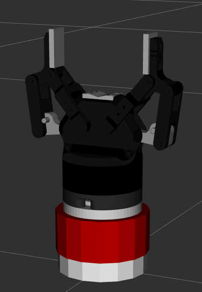
Inside of these files the configuration of adapter plates, sensors and grippers is defined. For example lets take a look at the left_gripper_macro.xacro. A launch file is provided to visualize the end effector isolated.
roslaunch invite_motoman_support test_left_gripper.launch
The left_gripper_macro.xacro defines the following links and joints in a tree-like structure (i.e. Each item is rigidly attached to the item below):
- 2-finger adaptive gripper from Robotiq with 85mm stroke
- Robotiq coupling (holding the electronic board of the gripper)
- Gripper adapter plate (Aluminium)
- DynPick force/torque sensor
- DynPick force/torque sensor adapter plate (Aluminium)
On Rviz on the Displays menu open the TF and the Tree item to see the tree structure defined in the xacro file.
NOTE: Similar analysis can be applied to the right gripper.
<!--Import macro from 2-finger adaptative robotiq gripper-->
<xacro:include filename="$(find robotiq_2f_85_gripper_visualization)/urdf/robotiq_arg2f_85_model_macro.xacro" />
Instanciate the gripper is defined
<!-- Instance of C3 85mm Model  -->
<xacro:robotiq_arg2f_85 prefix="<YOUR_GRIPPER_PREFIX>"/>
The gripper's base link has the name <YOUR_GRIPPER_PREFIX>robotiq_arg2f_base_link.

Invite-Robotics
-
Tutorials
