Feature Curved meshes
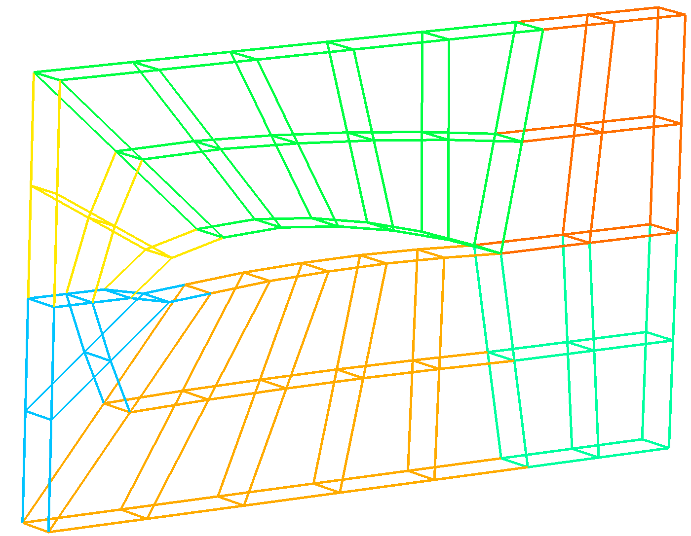
t8code has the functionality to read in a mesh file along with the CAD file used to generate the mesh. With this parallel read-in, we can generate curved adaptive meshes, as we call them. The curved adaptive meshes then are refined along the original CAD geometry. This is shown in the following figure.
You will find the code to this example in the tutorials/feature/t8_features_curved_meshes.cxx file and it creates the executable tutorials/feature/t8_features_curved_meshes.
To use this feature, we have to fulfill some requirements:
-
t8codehas to be linked toOpenCASCADE. This is done via the configure option--with-occ. - The used mesh has to be written in the
Gmsh's.msh4.X format. Moreover, the parametric export option fromGmshhas to be enabled. - The CAD file has to be written in
OpenCASCADE's.brepformat. - The
OpenCASCADEversion ofGmsh(Help button in theGmshGUI) must not be higher than theOpenCASCADEversiont8codeis linked to. - The mesh has to be hex/quad-only.
Generally, we can use every Software, which supports the .brep file format: FreeCAD, Gmsh, TiGL (all based on OpenCASCADE) to name a few. But we can also use OpenCASCADE itself.
Note: If you are using Gmsh for the generation of geometries, make sure to export the CAD geometry into a .brep file and import it again before meshing. Gmsh has an internal geometry indexing system based on the order of geometry generation. In the resulting .brep file, the geometries have different indices than in Gmsh itself. This can result in different .msh files in which the mesh nodes are attributed to the wrong geometries. By reloading the .brep file into Gmsh, Gmsh adapts the indexing of the .brep file.
Henceforth, we are going to generate a CAD geometry and mesh with Gmsh. For this, we use the scripting language .geo from Gmsh. We provide a 2D and 3D version of this example, but for now, we will take a look at the 3D version: If we take a look at the t8_features_curved_meshes_generate_cmesh.geo file in the tutorials directory, we can see how the CAD file and mesh are created.
You can execute this script with gmsh t8_features_curved_meshes_generate_cmesh.geo which will generate the files naca6412.brep and naca6412.msh.
After the two-dimensional definition of the NACA CAD geometry, it is extruded and meshed hex-only. Note, that the .brep file is reloaded before the meshing, as discussed before.

Now we can generate our curved, adaptive mesh. For this, we build our cmesh from the .msh and .brep files.
/* Read in the naca mesh from the msh file and the naca geometry from the brep file */
cmesh = t8_cmesh_from_msh_file (fileprefix, 0, sc_MPI_COMM_WORLD, 3, 0, occ || surface);
/* Construct a forest from the cmesh */
forest = t8_forest_new_uniform (cmesh,
                                t8_scheme_new_default_cxx (),
                                level, 0, comm);
Note, that we use the same msh file reader as usual. Hence, we only have to provide one file prefix and therefore the mesh and CAD files have to have the same file prefix.
After the import, we can handle the cmesh like normal, just the partitioning of the curved cmesh is not yet implemented. In this case, we create a new uniform forest and refine it according to two different criteria: We refine the elements based on their proximity to selected geometrical surfaces, and we let a plane move through the mesh and refine every element in a certain proximity.
Usage: To execute this refinement scheme in the tutorial, the -g option and the path to the files (-f) must be provided. Additionally, a uniform refinement level can be defined with -r and the levels of the ventral and dorsal surfaces can be set with -d and -d argument. This refinement scheme only works with curved meshes, since the information the refinement is based on, is not available in a linear mesh.
We can also use the CAD information of the cmesh for other purposes than curving the mesh. In the t8_naca_geometry_adapt_callback we use this information to identify elements touching the boundary layer of the NACA profile. For this, we define the geometries (in the 3D case surfaces), which should get refined, and we set a refinement level for them.
/* We retrieve the number of faces of this element. */
  const int           num_faces = ts->t8_element_num_faces (elements[0]);
  for (int iface = 0; iface < num_faces; ++iface) {
    /* We look if a face of the element lies on a face of the tree */
    if (ts->t8_element_is_root_boundary (elements[0], iface)) {
      /* We retrieve the face it lies on */
      int                 tree_face =
        ts->t8_element_tree_face (elements[0], iface);
      const t8_locidx_t   cmesh_ltreeid =
        t8_forest_ltreeid_to_cmesh_ltreeid (forest_from, which_tree);
      /* Retrieve the element dimension */
      const int           element_dim = t8_eclass_to_dimension[ts->eclass];
      /* We retrieve the geometry information of the tree.
       * In the 3D case, we look for linked surfaces, but in 2D, we look for linked edges. */
      const int           attribute_key =
        element_dim ==
        3 ? T8_CMESH_OCC_FACE_ATTRIBUTE_KEY : T8_CMESH_OCC_EDGE_ATTRIBUTE_KEY;
      const int          *linked_geometries =
        (const int *) t8_cmesh_get_attribute (t8_forest_get_cmesh (forest),
                                              t8_get_package_id (),
                                              attribute_key,
                                              cmesh_ltreeid);
      /* If the tree face has a linked surface and it is in the list we refine it */
      for (int igeom = 0; igeom < adapt_data->n_geometries; ++igeom) {
        if (linked_geometries[tree_face] == adapt_data->geometries[igeom] &&
            ts->t8_element_level (elements[0]) < adapt_data->levels[igeom]) {
          /* Refine this element */
          return 1;
        }
      }
    }
  }
  /* Do not change this element. */
  return 0;
In each adapt callback, we then iterate over each face of the current element and check if it lies on the boundary of its corresponding tree. If true, we can retrieve the CAD data of the tree's face and check if a specific CAD geometry is linked to it. This information we then use to decide, if the face gets refined or not.
Usage: To execute this refinement scheme in the tutorial, the -p option and the path to the files (-f) must be provided. Additionally, a uniform refinement level can be defined with -r and the starting and end point of the plane, as well as the number of time steps can be altered with the -x, -X and -t arguments. This refinement scheme works with the linear and curved geometry. By default, the linear geometry is used, but the curved one can be activated with -o.
In the other adapt callback (t8_naca_plane_adapt_callback), we move a plane through the mesh and refine all elements, whose centroids are in a certain proximity. We do this by looking at the x-coordinate of each centroid and by calculating its distance to the plane's x-coordinate. If the distance is under the user-defined threshold and the element's level is below the maximum refinement level, it gets refined. Otherwise, if the element's centroid is too far away and the level is above the minimum refinement level, the element gets coarsened.
To visualize the curved meshes, we have to link t8code against VTK with the --with-vtk compiler flag. The inbuilt VTK writer is not able to export the curvature of elements. But the geometry-based refinement of the elements is still visible without VTK linkage.
With a VTK-linked t8code, we can enable the curved flag of the t8_forest_write_vtk_ext function to export curved elements.
After loading the mesh into ParaView, we can set the Nonlinear Subdivision Level in the advanced properties of the loaded files to a value bigger than 0 to see the curvature in the mesh.
The same tutorial can also be used with 2D meshes. To do this, simply use the provided t8_features_curved_meshes_generate_cmesh_2d.geo script, to generate the 2D brep and msh file and use the CLI option -d2. Here, every routine works in the 2D dimension, but also a limitation becomes observable:
In the geometry refinement mode, the dorsal and ventral side of the NACA profile are not refined correctly.
